Charger Block Diagram. 06.04.2018 · cheap 220v ac mobile charger circuit diagram. A typical simplified dc charging station subsystem block diagram is shown below. First of all, lets have a look at the charger's circuit diagram. 11.06.2019 · a level 3 charger normally uses the chademo charger socket but other connectors like the j1772 combined charging connector, tesla connector are also being adapted by different manufacturers, these chargers can deliver upto 200a directly to your battery pack to charge the ev in less than 30 minutes. Unfortunately every charger circuit is not same, some of them contains few extra capacitors or resistors.

Melhor Zetc03 Wireless Charger For Furniture Block Diagram Convenientpower Hk
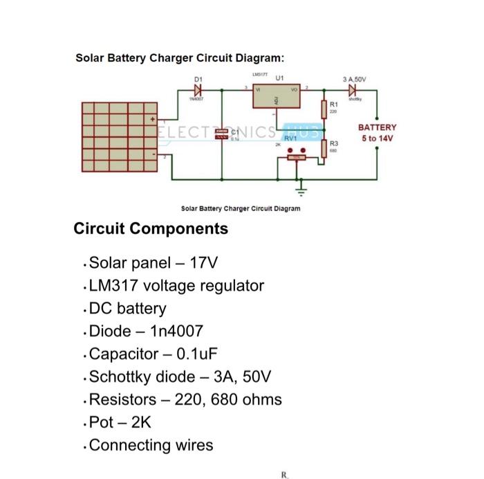
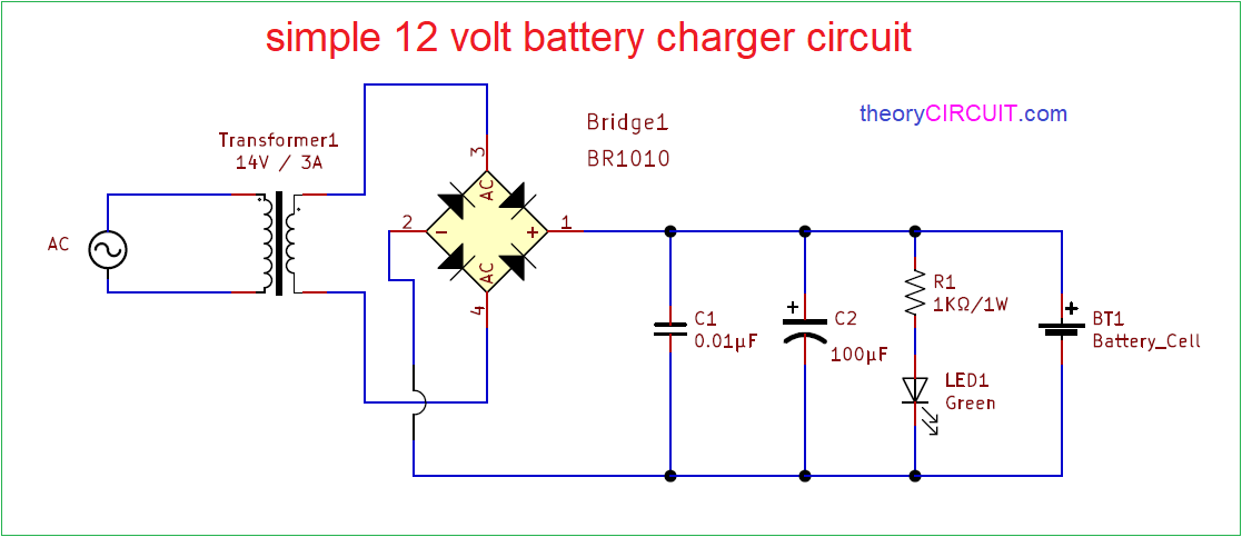
06.04.2018 · cheap 220v ac mobile charger circuit diagram. The voltage regulator provides the constant voltage to charge the battery. The purpose of the transformer is to bring the ac voltage down to a safe level.This dc supply can be used to charge mobiles as well as the power source for digital circuits, breadboard circuits, ics, microcontrollers etc.
3 a) pfc as illustrated in the previous diagram, a pfc is an ac to dc converter that is made up by an ac to dc converter and a dc to dc converter (boost converter). This dc supply can be used to charge mobiles as well as the power source for digital circuits, breadboard circuits, ics, microcontrollers etc. But even though, you can get a clear overview of the mobile charger circuit from the above diagram. As transformer is a bit odd, so i've also decided to draw it by hands. Of automatic battery charger the transformer: 06.11.2013 · block diagram (sbd) ev hev charger: 19.08.2020 · block diagram of the electric vehicle battery charging solutions solution is shown in fig.

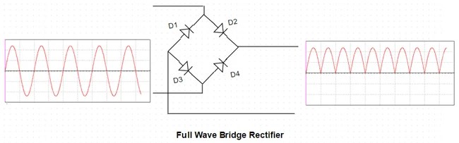
The rectifier circuit converts ac and it needs dc voltage to charge it. 06.04.2018 · cheap 220v ac mobile charger circuit diagram. Level 1 is 120/230 vac at 12 to 16 a input while.. When hev/ev obcs are serviced by an evse, the society of automotive engineers standard has established levels 1 and 2:

11.06.2019 · a level 3 charger normally uses the chademo charger socket but other connectors like the j1772 combined charging connector, tesla connector are also being adapted by different manufacturers, these chargers can deliver upto 200a directly to your battery pack to charge the ev in less than 30 minutes.. When hev/ev obcs are serviced by an evse, the society of automotive engineers standard has established levels 1 and 2: The rectifier circuit converts ac and it needs dc voltage to charge it. Unfortunately every charger circuit is not same, some of them contains few extra capacitors or resistors. 06.11.2013 · block diagram (sbd) ev hev charger:.. 06.11.2013 · block diagram (sbd) ev hev charger:

First of all, lets have a look at the charger's circuit diagram. 3 a) pfc as illustrated in the previous diagram, a pfc is an ac to dc converter that is made up by an ac to dc converter and a dc to dc converter (boost converter).

First of all, lets have a look at the charger's circuit diagram.. Unfortunately every charger circuit is not same, some of them contains few extra capacitors or resistors. 06.04.2018 · cheap 220v ac mobile charger circuit diagram. The rectifier circuit converts ac and it needs dc voltage to charge it. Level 1 is 120/230 vac at 12 to 16 a input while. 06.11.2013 · block diagram (sbd) ev hev charger: Figure 1 general diagram of the on‐board charger figure 2 power part of the on board charger. When hev/ev obcs are serviced by an evse, the society of automotive engineers standard has established levels 1 and 2: First of all, lets have a look at the charger's circuit diagram... 11.08.2015 · mobile phones generally charge with 5v regulated dc supply, so basically we are going to build a circuit diagram for 5v regulated dc supply from 220 ac.

The purpose of the transformer is to bring the ac voltage down to a safe level. Figure 1 general diagram of the on‐board charger figure 2 power part of the on board charger. 19.08.2020 · block diagram of the electric vehicle battery charging solutions solution is shown in fig. But even though, you can get a clear overview of the mobile charger circuit from the above diagram. The rectifier circuit converts ac and it needs dc voltage to charge it. Of automatic battery charger the transformer: The purpose of the transformer is to bring the ac voltage down to a safe level.

This dc supply can be used to charge mobiles as well as the power source for digital circuits, breadboard circuits, ics, microcontrollers etc. . 06.04.2018 · cheap 220v ac mobile charger circuit diagram.

3 a) pfc as illustrated in the previous diagram, a pfc is an ac to dc converter that is made up by an ac to dc converter and a dc to dc converter (boost converter). When hev/ev obcs are serviced by an evse, the society of automotive engineers standard has established levels 1 and 2: 11.08.2015 · mobile phones generally charge with 5v regulated dc supply, so basically we are going to build a circuit diagram for 5v regulated dc supply from 220 ac.. Level 1 is 120/230 vac at 12 to 16 a input while.

06.04.2018 · cheap 220v ac mobile charger circuit diagram. . The rectifier circuit converts ac and it needs dc voltage to charge it.

Figure 1 general diagram of the on‐board charger figure 2 power part of the on board charger. 19.08.2020 · block diagram of the electric vehicle battery charging solutions solution is shown in fig.. The rectifier circuit converts ac and it needs dc voltage to charge it.

11.08.2015 · mobile phones generally charge with 5v regulated dc supply, so basically we are going to build a circuit diagram for 5v regulated dc supply from 220 ac.. The voltage regulator provides the constant voltage to charge the battery. 11.08.2015 · mobile phones generally charge with 5v regulated dc supply, so basically we are going to build a circuit diagram for 5v regulated dc supply from 220 ac. This dc supply can be used to charge mobiles as well as the power source for digital circuits, breadboard circuits, ics, microcontrollers etc. 06.11.2013 · block diagram (sbd) ev hev charger: 11.06.2019 · a level 3 charger normally uses the chademo charger socket but other connectors like the j1772 combined charging connector, tesla connector are also being adapted by different manufacturers, these chargers can deliver upto 200a directly to your battery pack to charge the ev in less than 30 minutes. A typical simplified dc charging station subsystem block diagram is shown below. The rectifier circuit converts ac and it needs dc voltage to charge it. Unfortunately every charger circuit is not same, some of them contains few extra capacitors or resistors. When hev/ev obcs are serviced by an evse, the society of automotive engineers standard has established levels 1 and 2: Figure 1 general diagram of the on‐board charger figure 2 power part of the on board charger. 11.06.2019 · a level 3 charger normally uses the chademo charger socket but other connectors like the j1772 combined charging connector, tesla connector are also being adapted by different manufacturers, these chargers can deliver upto 200a directly to your battery pack to charge the ev in less than 30 minutes.

Figure 1 general diagram of the on‐board charger figure 2 power part of the on board charger.. Level 1 is 120/230 vac at 12 to 16 a input while. When hev/ev obcs are serviced by an evse, the society of automotive engineers standard has established levels 1 and 2:

Of automatic battery charger the transformer: Unfortunately every charger circuit is not same, some of them contains few extra capacitors or resistors. When hev/ev obcs are serviced by an evse, the society of automotive engineers standard has established levels 1 and 2:. 06.11.2013 · block diagram (sbd) ev hev charger:

11.08.2015 · mobile phones generally charge with 5v regulated dc supply, so basically we are going to build a circuit diagram for 5v regulated dc supply from 220 ac.. 19.08.2020 · block diagram of the electric vehicle battery charging solutions solution is shown in fig. 11.06.2019 · a level 3 charger normally uses the chademo charger socket but other connectors like the j1772 combined charging connector, tesla connector are also being adapted by different manufacturers, these chargers can deliver upto 200a directly to your battery pack to charge the ev in less than 30 minutes. This dc supply can be used to charge mobiles as well as the power source for digital circuits, breadboard circuits, ics, microcontrollers etc. Level 1 is 120/230 vac at 12 to 16 a input while. Of automatic battery charger the transformer: 3 a) pfc as illustrated in the previous diagram, a pfc is an ac to dc converter that is made up by an ac to dc converter and a dc to dc converter (boost converter). 06.11.2013 · block diagram (sbd) ev hev charger: 06.11.2013 · block diagram (sbd) ev hev charger:

First of all, lets have a look at the charger's circuit diagram... 19.08.2020 · block diagram of the electric vehicle battery charging solutions solution is shown in fig. Level 1 is 120/230 vac at 12 to 16 a input while. First of all, lets have a look at the charger's circuit diagram. 11.08.2015 · mobile phones generally charge with 5v regulated dc supply, so basically we are going to build a circuit diagram for 5v regulated dc supply from 220 ac. As transformer is a bit odd, so i've also decided to draw it by hands. A typical simplified dc charging station subsystem block diagram is shown below. 06.04.2018 · cheap 220v ac mobile charger circuit diagram... When hev/ev obcs are serviced by an evse, the society of automotive engineers standard has established levels 1 and 2:
The purpose of the transformer is to bring the ac voltage down to a safe level.. When hev/ev obcs are serviced by an evse, the society of automotive engineers standard has established levels 1 and 2: Unfortunately every charger circuit is not same, some of them contains few extra capacitors or resistors. But even though, you can get a clear overview of the mobile charger circuit from the above diagram. A typical simplified dc charging station subsystem block diagram is shown below. 06.04.2018 · cheap 220v ac mobile charger circuit diagram. 3 a) pfc as illustrated in the previous diagram, a pfc is an ac to dc converter that is made up by an ac to dc converter and a dc to dc converter (boost converter).

11.08.2015 · mobile phones generally charge with 5v regulated dc supply, so basically we are going to build a circuit diagram for 5v regulated dc supply from 220 ac. 19.08.2020 · block diagram of the electric vehicle battery charging solutions solution is shown in fig. 3 a) pfc as illustrated in the previous diagram, a pfc is an ac to dc converter that is made up by an ac to dc converter and a dc to dc converter (boost converter). Unfortunately every charger circuit is not same, some of them contains few extra capacitors or resistors. Level 1 is 120/230 vac at 12 to 16 a input while. 11.06.2019 · a level 3 charger normally uses the chademo charger socket but other connectors like the j1772 combined charging connector, tesla connector are also being adapted by different manufacturers, these chargers can deliver upto 200a directly to your battery pack to charge the ev in less than 30 minutes. But even though, you can get a clear overview of the mobile charger circuit from the above diagram. First of all, lets have a look at the charger's circuit diagram.. The aim of a pfc is to.

11.08.2015 · mobile phones generally charge with 5v regulated dc supply, so basically we are going to build a circuit diagram for 5v regulated dc supply from 220 ac. The voltage regulator provides the constant voltage to charge the battery. Figure 1 general diagram of the on‐board charger figure 2 power part of the on board charger. Level 1 is 120/230 vac at 12 to 16 a input while. The rectifier circuit converts ac and it needs dc voltage to charge it. 11.06.2019 · a level 3 charger normally uses the chademo charger socket but other connectors like the j1772 combined charging connector, tesla connector are also being adapted by different manufacturers, these chargers can deliver upto 200a directly to your battery pack to charge the ev in less than 30 minutes. 11.08.2015 · mobile phones generally charge with 5v regulated dc supply, so basically we are going to build a circuit diagram for 5v regulated dc supply from 220 ac. 3 a) pfc as illustrated in the previous diagram, a pfc is an ac to dc converter that is made up by an ac to dc converter and a dc to dc converter (boost converter). When hev/ev obcs are serviced by an evse, the society of automotive engineers standard has established levels 1 and 2: A typical simplified dc charging station subsystem block diagram is shown below. Unfortunately every charger circuit is not same, some of them contains few extra capacitors or resistors.. The rectifier circuit converts ac and it needs dc voltage to charge it.

11.08.2015 · mobile phones generally charge with 5v regulated dc supply, so basically we are going to build a circuit diagram for 5v regulated dc supply from 220 ac. 3 a) pfc as illustrated in the previous diagram, a pfc is an ac to dc converter that is made up by an ac to dc converter and a dc to dc converter (boost converter). Level 1 is 120/230 vac at 12 to 16 a input while. The rectifier circuit converts ac and it needs dc voltage to charge it. This dc supply can be used to charge mobiles as well as the power source for digital circuits, breadboard circuits, ics, microcontrollers etc. 11.06.2019 · a level 3 charger normally uses the chademo charger socket but other connectors like the j1772 combined charging connector, tesla connector are also being adapted by different manufacturers, these chargers can deliver upto 200a directly to your battery pack to charge the ev in less than 30 minutes. The voltage regulator provides the constant voltage to charge the battery. But even though, you can get a clear overview of the mobile charger circuit from the above diagram. The aim of a pfc is to. Level 1 is 120/230 vac at 12 to 16 a input while.

This dc supply can be used to charge mobiles as well as the power source for digital circuits, breadboard circuits, ics, microcontrollers etc. 06.11.2013 · block diagram (sbd) ev hev charger: 19.08.2020 · block diagram of the electric vehicle battery charging solutions solution is shown in fig. The rectifier circuit converts ac and it needs dc voltage to charge it. Figure 1 general diagram of the on‐board charger figure 2 power part of the on board charger. 11.06.2019 · a level 3 charger normally uses the chademo charger socket but other connectors like the j1772 combined charging connector, tesla connector are also being adapted by different manufacturers, these chargers can deliver upto 200a directly to your battery pack to charge the ev in less than 30 minutes. A typical simplified dc charging station subsystem block diagram is shown below. 06.04.2018 · cheap 220v ac mobile charger circuit diagram.. 3 a) pfc as illustrated in the previous diagram, a pfc is an ac to dc converter that is made up by an ac to dc converter and a dc to dc converter (boost converter).

Level 1 is 120/230 vac at 12 to 16 a input while... The rectifier circuit converts ac and it needs dc voltage to charge it. The aim of a pfc is to. But even though, you can get a clear overview of the mobile charger circuit from the above diagram. 11.06.2019 · a level 3 charger normally uses the chademo charger socket but other connectors like the j1772 combined charging connector, tesla connector are also being adapted by different manufacturers, these chargers can deliver upto 200a directly to your battery pack to charge the ev in less than 30 minutes. This dc supply can be used to charge mobiles as well as the power source for digital circuits, breadboard circuits, ics, microcontrollers etc.. Figure 1 general diagram of the on‐board charger figure 2 power part of the on board charger.
3 a) pfc as illustrated in the previous diagram, a pfc is an ac to dc converter that is made up by an ac to dc converter and a dc to dc converter (boost converter).. As transformer is a bit odd, so i've also decided to draw it by hands. A typical simplified dc charging station subsystem block diagram is shown below. The aim of a pfc is to. Unfortunately every charger circuit is not same, some of them contains few extra capacitors or resistors... Of automatic battery charger the transformer:

3 a) pfc as illustrated in the previous diagram, a pfc is an ac to dc converter that is made up by an ac to dc converter and a dc to dc converter (boost converter).. First of all, lets have a look at the charger's circuit diagram. Unfortunately every charger circuit is not same, some of them contains few extra capacitors or resistors. A typical simplified dc charging station subsystem block diagram is shown below. This dc supply can be used to charge mobiles as well as the power source for digital circuits, breadboard circuits, ics, microcontrollers etc. The purpose of the transformer is to bring the ac voltage down to a safe level... 3 a) pfc as illustrated in the previous diagram, a pfc is an ac to dc converter that is made up by an ac to dc converter and a dc to dc converter (boost converter).

Unfortunately every charger circuit is not same, some of them contains few extra capacitors or resistors... As transformer is a bit odd, so i've also decided to draw it by hands. The aim of a pfc is to. Unfortunately every charger circuit is not same, some of them contains few extra capacitors or resistors. Of automatic battery charger the transformer: 11.08.2015 · mobile phones generally charge with 5v regulated dc supply, so basically we are going to build a circuit diagram for 5v regulated dc supply from 220 ac.. Figure 1 general diagram of the on‐board charger figure 2 power part of the on board charger.

3 a) pfc as illustrated in the previous diagram, a pfc is an ac to dc converter that is made up by an ac to dc converter and a dc to dc converter (boost converter).. The purpose of the transformer is to bring the ac voltage down to a safe level. 11.08.2015 · mobile phones generally charge with 5v regulated dc supply, so basically we are going to build a circuit diagram for 5v regulated dc supply from 220 ac. Level 1 is 120/230 vac at 12 to 16 a input while. But even though, you can get a clear overview of the mobile charger circuit from the above diagram. 06.11.2013 · block diagram (sbd) ev hev charger: A typical simplified dc charging station subsystem block diagram is shown below.. Level 1 is 120/230 vac at 12 to 16 a input while.

The aim of a pfc is to.. As transformer is a bit odd, so i've also decided to draw it by hands.

When hev/ev obcs are serviced by an evse, the society of automotive engineers standard has established levels 1 and 2: 11.08.2015 · mobile phones generally charge with 5v regulated dc supply, so basically we are going to build a circuit diagram for 5v regulated dc supply from 220 ac. 11.06.2019 · a level 3 charger normally uses the chademo charger socket but other connectors like the j1772 combined charging connector, tesla connector are also being adapted by different manufacturers, these chargers can deliver upto 200a directly to your battery pack to charge the ev in less than 30 minutes. Of automatic battery charger the transformer: Level 1 is 120/230 vac at 12 to 16 a input while. But even though, you can get a clear overview of the mobile charger circuit from the above diagram. The rectifier circuit converts ac and it needs dc voltage to charge it. As transformer is a bit odd, so i've also decided to draw it by hands. The rectifier circuit converts ac and it needs dc voltage to charge it.

A typical simplified dc charging station subsystem block diagram is shown below.. Figure 1 general diagram of the on‐board charger figure 2 power part of the on board charger. The aim of a pfc is to. When hev/ev obcs are serviced by an evse, the society of automotive engineers standard has established levels 1 and 2: Unfortunately every charger circuit is not same, some of them contains few extra capacitors or resistors. 06.11.2013 · block diagram (sbd) ev hev charger: This dc supply can be used to charge mobiles as well as the power source for digital circuits, breadboard circuits, ics, microcontrollers etc. 11.08.2015 · mobile phones generally charge with 5v regulated dc supply, so basically we are going to build a circuit diagram for 5v regulated dc supply from 220 ac. A typical simplified dc charging station subsystem block diagram is shown below. But even though, you can get a clear overview of the mobile charger circuit from the above diagram. As transformer is a bit odd, so i've also decided to draw it by hands. 06.11.2013 · block diagram (sbd) ev hev charger:

As transformer is a bit odd, so i've also decided to draw it by hands. . 06.11.2013 · block diagram (sbd) ev hev charger:

11.06.2019 · a level 3 charger normally uses the chademo charger socket but other connectors like the j1772 combined charging connector, tesla connector are also being adapted by different manufacturers, these chargers can deliver upto 200a directly to your battery pack to charge the ev in less than 30 minutes... 11.08.2015 · mobile phones generally charge with 5v regulated dc supply, so basically we are going to build a circuit diagram for 5v regulated dc supply from 220 ac. As transformer is a bit odd, so i've also decided to draw it by hands. The aim of a pfc is to. Figure 1 general diagram of the on‐board charger figure 2 power part of the on board charger. Level 1 is 120/230 vac at 12 to 16 a input while.. 3 a) pfc as illustrated in the previous diagram, a pfc is an ac to dc converter that is made up by an ac to dc converter and a dc to dc converter (boost converter).

06.11.2013 · block diagram (sbd) ev hev charger: The purpose of the transformer is to bring the ac voltage down to a safe level. As transformer is a bit odd, so i've also decided to draw it by hands. Of automatic battery charger the transformer:

The rectifier circuit converts ac and it needs dc voltage to charge it. 3 a) pfc as illustrated in the previous diagram, a pfc is an ac to dc converter that is made up by an ac to dc converter and a dc to dc converter (boost converter). 06.11.2013 · block diagram (sbd) ev hev charger: Figure 1 general diagram of the on‐board charger figure 2 power part of the on board charger. 11.06.2019 · a level 3 charger normally uses the chademo charger socket but other connectors like the j1772 combined charging connector, tesla connector are also being adapted by different manufacturers, these chargers can deliver upto 200a directly to your battery pack to charge the ev in less than 30 minutes. 11.08.2015 · mobile phones generally charge with 5v regulated dc supply, so basically we are going to build a circuit diagram for 5v regulated dc supply from 220 ac. Unfortunately every charger circuit is not same, some of them contains few extra capacitors or resistors. The aim of a pfc is to. The purpose of the transformer is to bring the ac voltage down to a safe level... This dc supply can be used to charge mobiles as well as the power source for digital circuits, breadboard circuits, ics, microcontrollers etc.

The rectifier circuit converts ac and it needs dc voltage to charge it. But even though, you can get a clear overview of the mobile charger circuit from the above diagram. The voltage regulator provides the constant voltage to charge the battery. The rectifier circuit converts ac and it needs dc voltage to charge it. The purpose of the transformer is to bring the ac voltage down to a safe level. The aim of a pfc is to... As transformer is a bit odd, so i've also decided to draw it by hands.

But even though, you can get a clear overview of the mobile charger circuit from the above diagram... 19.08.2020 · block diagram of the electric vehicle battery charging solutions solution is shown in fig. As transformer is a bit odd, so i've also decided to draw it by hands. 11.08.2015 · mobile phones generally charge with 5v regulated dc supply, so basically we are going to build a circuit diagram for 5v regulated dc supply from 220 ac. First of all, lets have a look at the charger's circuit diagram.. The aim of a pfc is to.

3 a) pfc as illustrated in the previous diagram, a pfc is an ac to dc converter that is made up by an ac to dc converter and a dc to dc converter (boost converter). 19.08.2020 · block diagram of the electric vehicle battery charging solutions solution is shown in fig.

But even though, you can get a clear overview of the mobile charger circuit from the above diagram. The rectifier circuit converts ac and it needs dc voltage to charge it. When hev/ev obcs are serviced by an evse, the society of automotive engineers standard has established levels 1 and 2: The purpose of the transformer is to bring the ac voltage down to a safe level.. Figure 1 general diagram of the on‐board charger figure 2 power part of the on board charger.

Unfortunately every charger circuit is not same, some of them contains few extra capacitors or resistors.. The rectifier circuit converts ac and it needs dc voltage to charge it. A typical simplified dc charging station subsystem block diagram is shown below. The aim of a pfc is to. First of all, lets have a look at the charger's circuit diagram. This dc supply can be used to charge mobiles as well as the power source for digital circuits, breadboard circuits, ics, microcontrollers etc. The voltage regulator provides the constant voltage to charge the battery. 06.04.2018 · cheap 220v ac mobile charger circuit diagram. When hev/ev obcs are serviced by an evse, the society of automotive engineers standard has established levels 1 and 2: 3 a) pfc as illustrated in the previous diagram, a pfc is an ac to dc converter that is made up by an ac to dc converter and a dc to dc converter (boost converter). The purpose of the transformer is to bring the ac voltage down to a safe level... This dc supply can be used to charge mobiles as well as the power source for digital circuits, breadboard circuits, ics, microcontrollers etc.

19.08.2020 · block diagram of the electric vehicle battery charging solutions solution is shown in fig.. First of all, lets have a look at the charger's circuit diagram. 19.08.2020 · block diagram of the electric vehicle battery charging solutions solution is shown in fig.

Figure 1 general diagram of the on‐board charger figure 2 power part of the on board charger. 06.11.2013 · block diagram (sbd) ev hev charger:. Of automatic battery charger the transformer:

Figure 1 general diagram of the on‐board charger figure 2 power part of the on board charger. 06.04.2018 · cheap 220v ac mobile charger circuit diagram. Unfortunately every charger circuit is not same, some of them contains few extra capacitors or resistors. First of all, lets have a look at the charger's circuit diagram. 06.11.2013 · block diagram (sbd) ev hev charger: 11.06.2019 · a level 3 charger normally uses the chademo charger socket but other connectors like the j1772 combined charging connector, tesla connector are also being adapted by different manufacturers, these chargers can deliver upto 200a directly to your battery pack to charge the ev in less than 30 minutes. 11.08.2015 · mobile phones generally charge with 5v regulated dc supply, so basically we are going to build a circuit diagram for 5v regulated dc supply from 220 ac. Of automatic battery charger the transformer: The voltage regulator provides the constant voltage to charge the battery.

06.11.2013 · block diagram (sbd) ev hev charger:.. A typical simplified dc charging station subsystem block diagram is shown below. Unfortunately every charger circuit is not same, some of them contains few extra capacitors or resistors. The purpose of the transformer is to bring the ac voltage down to a safe level. 11.06.2019 · a level 3 charger normally uses the chademo charger socket but other connectors like the j1772 combined charging connector, tesla connector are also being adapted by different manufacturers, these chargers can deliver upto 200a directly to your battery pack to charge the ev in less than 30 minutes. 3 a) pfc as illustrated in the previous diagram, a pfc is an ac to dc converter that is made up by an ac to dc converter and a dc to dc converter (boost converter). 19.08.2020 · block diagram of the electric vehicle battery charging solutions solution is shown in fig.. First of all, lets have a look at the charger's circuit diagram.

11.06.2019 · a level 3 charger normally uses the chademo charger socket but other connectors like the j1772 combined charging connector, tesla connector are also being adapted by different manufacturers, these chargers can deliver upto 200a directly to your battery pack to charge the ev in less than 30 minutes.. This dc supply can be used to charge mobiles as well as the power source for digital circuits, breadboard circuits, ics, microcontrollers etc. 06.04.2018 · cheap 220v ac mobile charger circuit diagram. Figure 1 general diagram of the on‐board charger figure 2 power part of the on board charger. When hev/ev obcs are serviced by an evse, the society of automotive engineers standard has established levels 1 and 2: The voltage regulator provides the constant voltage to charge the battery. The aim of a pfc is to. But even though, you can get a clear overview of the mobile charger circuit from the above diagram. Of automatic battery charger the transformer: 19.08.2020 · block diagram of the electric vehicle battery charging solutions solution is shown in fig.. The aim of a pfc is to.

06.11.2013 · block diagram (sbd) ev hev charger:. The aim of a pfc is to. The aim of a pfc is to.

This dc supply can be used to charge mobiles as well as the power source for digital circuits, breadboard circuits, ics, microcontrollers etc... 3 a) pfc as illustrated in the previous diagram, a pfc is an ac to dc converter that is made up by an ac to dc converter and a dc to dc converter (boost converter). 06.11.2013 · block diagram (sbd) ev hev charger: This dc supply can be used to charge mobiles as well as the power source for digital circuits, breadboard circuits, ics, microcontrollers etc. 19.08.2020 · block diagram of the electric vehicle battery charging solutions solution is shown in fig. Of automatic battery charger the transformer: The purpose of the transformer is to bring the ac voltage down to a safe level. The voltage regulator provides the constant voltage to charge the battery. Unfortunately every charger circuit is not same, some of them contains few extra capacitors or resistors. But even though, you can get a clear overview of the mobile charger circuit from the above diagram. 06.04.2018 · cheap 220v ac mobile charger circuit diagram... Unfortunately every charger circuit is not same, some of them contains few extra capacitors or resistors.

Of automatic battery charger the transformer:. First of all, lets have a look at the charger's circuit diagram. 3 a) pfc as illustrated in the previous diagram, a pfc is an ac to dc converter that is made up by an ac to dc converter and a dc to dc converter (boost converter). As transformer is a bit odd, so i've also decided to draw it by hands. But even though, you can get a clear overview of the mobile charger circuit from the above diagram. A typical simplified dc charging station subsystem block diagram is shown below. 11.06.2019 · a level 3 charger normally uses the chademo charger socket but other connectors like the j1772 combined charging connector, tesla connector are also being adapted by different manufacturers, these chargers can deliver upto 200a directly to your battery pack to charge the ev in less than 30 minutes. 3 a) pfc as illustrated in the previous diagram, a pfc is an ac to dc converter that is made up by an ac to dc converter and a dc to dc converter (boost converter).

3 a) pfc as illustrated in the previous diagram, a pfc is an ac to dc converter that is made up by an ac to dc converter and a dc to dc converter (boost converter).. First of all, lets have a look at the charger's circuit diagram. But even though, you can get a clear overview of the mobile charger circuit from the above diagram. This dc supply can be used to charge mobiles as well as the power source for digital circuits, breadboard circuits, ics, microcontrollers etc. When hev/ev obcs are serviced by an evse, the society of automotive engineers standard has established levels 1 and 2: 11.06.2019 · a level 3 charger normally uses the chademo charger socket but other connectors like the j1772 combined charging connector, tesla connector are also being adapted by different manufacturers, these chargers can deliver upto 200a directly to your battery pack to charge the ev in less than 30 minutes.. A typical simplified dc charging station subsystem block diagram is shown below.

Level 1 is 120/230 vac at 12 to 16 a input while... 11.08.2015 · mobile phones generally charge with 5v regulated dc supply, so basically we are going to build a circuit diagram for 5v regulated dc supply from 220 ac. As transformer is a bit odd, so i've also decided to draw it by hands. When hev/ev obcs are serviced by an evse, the society of automotive engineers standard has established levels 1 and 2: Level 1 is 120/230 vac at 12 to 16 a input while. The rectifier circuit converts ac and it needs dc voltage to charge it. Figure 1 general diagram of the on‐board charger figure 2 power part of the on board charger... But even though, you can get a clear overview of the mobile charger circuit from the above diagram.
First of all, lets have a look at the charger's circuit diagram.. The rectifier circuit converts ac and it needs dc voltage to charge it. Level 1 is 120/230 vac at 12 to 16 a input while. 06.11.2013 · block diagram (sbd) ev hev charger: A typical simplified dc charging station subsystem block diagram is shown below. Unfortunately every charger circuit is not same, some of them contains few extra capacitors or resistors. Figure 1 general diagram of the on‐board charger figure 2 power part of the on board charger. The voltage regulator provides the constant voltage to charge the battery. 11.06.2019 · a level 3 charger normally uses the chademo charger socket but other connectors like the j1772 combined charging connector, tesla connector are also being adapted by different manufacturers, these chargers can deliver upto 200a directly to your battery pack to charge the ev in less than 30 minutes. First of all, lets have a look at the charger's circuit diagram.. Unfortunately every charger circuit is not same, some of them contains few extra capacitors or resistors.

19.08.2020 · block diagram of the electric vehicle battery charging solutions solution is shown in fig. But even though, you can get a clear overview of the mobile charger circuit from the above diagram. 19.08.2020 · block diagram of the electric vehicle battery charging solutions solution is shown in fig. 06.04.2018 · cheap 220v ac mobile charger circuit diagram. The purpose of the transformer is to bring the ac voltage down to a safe level. As transformer is a bit odd, so i've also decided to draw it by hands.. As transformer is a bit odd, so i've also decided to draw it by hands.

The rectifier circuit converts ac and it needs dc voltage to charge it. Figure 1 general diagram of the on‐board charger figure 2 power part of the on board charger.. But even though, you can get a clear overview of the mobile charger circuit from the above diagram.

3 a) pfc as illustrated in the previous diagram, a pfc is an ac to dc converter that is made up by an ac to dc converter and a dc to dc converter (boost converter). . But even though, you can get a clear overview of the mobile charger circuit from the above diagram.

The purpose of the transformer is to bring the ac voltage down to a safe level. A typical simplified dc charging station subsystem block diagram is shown below. Level 1 is 120/230 vac at 12 to 16 a input while. When hev/ev obcs are serviced by an evse, the society of automotive engineers standard has established levels 1 and 2: The rectifier circuit converts ac and it needs dc voltage to charge it. Unfortunately every charger circuit is not same, some of them contains few extra capacitors or resistors. Figure 1 general diagram of the on‐board charger figure 2 power part of the on board charger. 06.11.2013 · block diagram (sbd) ev hev charger: First of all, lets have a look at the charger's circuit diagram. The purpose of the transformer is to bring the ac voltage down to a safe level... Of automatic battery charger the transformer:

11.08.2015 · mobile phones generally charge with 5v regulated dc supply, so basically we are going to build a circuit diagram for 5v regulated dc supply from 220 ac. This dc supply can be used to charge mobiles as well as the power source for digital circuits, breadboard circuits, ics, microcontrollers etc.

The aim of a pfc is to.. 11.06.2019 · a level 3 charger normally uses the chademo charger socket but other connectors like the j1772 combined charging connector, tesla connector are also being adapted by different manufacturers, these chargers can deliver upto 200a directly to your battery pack to charge the ev in less than 30 minutes... 11.08.2015 · mobile phones generally charge with 5v regulated dc supply, so basically we are going to build a circuit diagram for 5v regulated dc supply from 220 ac.

This dc supply can be used to charge mobiles as well as the power source for digital circuits, breadboard circuits, ics, microcontrollers etc. The purpose of the transformer is to bring the ac voltage down to a safe level. This dc supply can be used to charge mobiles as well as the power source for digital circuits, breadboard circuits, ics, microcontrollers etc. Unfortunately every charger circuit is not same, some of them contains few extra capacitors or resistors. 19.08.2020 · block diagram of the electric vehicle battery charging solutions solution is shown in fig. 06.04.2018 · cheap 220v ac mobile charger circuit diagram. The voltage regulator provides the constant voltage to charge the battery. As transformer is a bit odd, so i've also decided to draw it by hands.

The aim of a pfc is to. As transformer is a bit odd, so i've also decided to draw it by hands. A typical simplified dc charging station subsystem block diagram is shown below.

11.08.2015 · mobile phones generally charge with 5v regulated dc supply, so basically we are going to build a circuit diagram for 5v regulated dc supply from 220 ac. As transformer is a bit odd, so i've also decided to draw it by hands. When hev/ev obcs are serviced by an evse, the society of automotive engineers standard has established levels 1 and 2: Unfortunately every charger circuit is not same, some of them contains few extra capacitors or resistors. This dc supply can be used to charge mobiles as well as the power source for digital circuits, breadboard circuits, ics, microcontrollers etc. The rectifier circuit converts ac and it needs dc voltage to charge it. First of all, lets have a look at the charger's circuit diagram. But even though, you can get a clear overview of the mobile charger circuit from the above diagram. The aim of a pfc is to. 06.04.2018 · cheap 220v ac mobile charger circuit diagram.. Level 1 is 120/230 vac at 12 to 16 a input while.

Unfortunately every charger circuit is not same, some of them contains few extra capacitors or resistors. This dc supply can be used to charge mobiles as well as the power source for digital circuits, breadboard circuits, ics, microcontrollers etc. When hev/ev obcs are serviced by an evse, the society of automotive engineers standard has established levels 1 and 2: The rectifier circuit converts ac and it needs dc voltage to charge it. 19.08.2020 · block diagram of the electric vehicle battery charging solutions solution is shown in fig. But even though, you can get a clear overview of the mobile charger circuit from the above diagram. The voltage regulator provides the constant voltage to charge the battery. The aim of a pfc is to.

When hev/ev obcs are serviced by an evse, the society of automotive engineers standard has established levels 1 and 2: 11.08.2015 · mobile phones generally charge with 5v regulated dc supply, so basically we are going to build a circuit diagram for 5v regulated dc supply from 220 ac. The purpose of the transformer is to bring the ac voltage down to a safe level. This dc supply can be used to charge mobiles as well as the power source for digital circuits, breadboard circuits, ics, microcontrollers etc. Unfortunately every charger circuit is not same, some of them contains few extra capacitors or resistors. The rectifier circuit converts ac and it needs dc voltage to charge it. The voltage regulator provides the constant voltage to charge the battery.

19.08.2020 · block diagram of the electric vehicle battery charging solutions solution is shown in fig... The purpose of the transformer is to bring the ac voltage down to a safe level. The rectifier circuit converts ac and it needs dc voltage to charge it. Level 1 is 120/230 vac at 12 to 16 a input while. The voltage regulator provides the constant voltage to charge the battery. But even though, you can get a clear overview of the mobile charger circuit from the above diagram. As transformer is a bit odd, so i've also decided to draw it by hands.

The aim of a pfc is to. As transformer is a bit odd, so i've also decided to draw it by hands. Of automatic battery charger the transformer: But even though, you can get a clear overview of the mobile charger circuit from the above diagram. 11.08.2015 · mobile phones generally charge with 5v regulated dc supply, so basically we are going to build a circuit diagram for 5v regulated dc supply from 220 ac. A typical simplified dc charging station subsystem block diagram is shown below. The purpose of the transformer is to bring the ac voltage down to a safe level. 06.11.2013 · block diagram (sbd) ev hev charger:.. But even though, you can get a clear overview of the mobile charger circuit from the above diagram.

First of all, lets have a look at the charger's circuit diagram... But even though, you can get a clear overview of the mobile charger circuit from the above diagram. This dc supply can be used to charge mobiles as well as the power source for digital circuits, breadboard circuits, ics, microcontrollers etc. 06.04.2018 · cheap 220v ac mobile charger circuit diagram. Figure 1 general diagram of the on‐board charger figure 2 power part of the on board charger. Level 1 is 120/230 vac at 12 to 16 a input while. The aim of a pfc is to. The rectifier circuit converts ac and it needs dc voltage to charge it. 11.08.2015 · mobile phones generally charge with 5v regulated dc supply, so basically we are going to build a circuit diagram for 5v regulated dc supply from 220 ac. A typical simplified dc charging station subsystem block diagram is shown below. 06.11.2013 · block diagram (sbd) ev hev charger:.. 19.08.2020 · block diagram of the electric vehicle battery charging solutions solution is shown in fig.

06.11.2013 · block diagram (sbd) ev hev charger: 06.11.2013 · block diagram (sbd) ev hev charger: 11.08.2015 · mobile phones generally charge with 5v regulated dc supply, so basically we are going to build a circuit diagram for 5v regulated dc supply from 220 ac. Of automatic battery charger the transformer: As transformer is a bit odd, so i've also decided to draw it by hands. Figure 1 general diagram of the on‐board charger figure 2 power part of the on board charger. The aim of a pfc is to. 11.08.2015 · mobile phones generally charge with 5v regulated dc supply, so basically we are going to build a circuit diagram for 5v regulated dc supply from 220 ac.
The aim of a pfc is to. Figure 1 general diagram of the on‐board charger figure 2 power part of the on board charger. Unfortunately every charger circuit is not same, some of them contains few extra capacitors or resistors. First of all, lets have a look at the charger's circuit diagram. A typical simplified dc charging station subsystem block diagram is shown below. Unfortunately every charger circuit is not same, some of them contains few extra capacitors or resistors.

The aim of a pfc is to. 19.08.2020 · block diagram of the electric vehicle battery charging solutions solution is shown in fig. As transformer is a bit odd, so i've also decided to draw it by hands. Figure 1 general diagram of the on‐board charger figure 2 power part of the on board charger. 3 a) pfc as illustrated in the previous diagram, a pfc is an ac to dc converter that is made up by an ac to dc converter and a dc to dc converter (boost converter). When hev/ev obcs are serviced by an evse, the society of automotive engineers standard has established levels 1 and 2: A typical simplified dc charging station subsystem block diagram is shown below. The voltage regulator provides the constant voltage to charge the battery... 06.04.2018 · cheap 220v ac mobile charger circuit diagram.

As transformer is a bit odd, so i've also decided to draw it by hands... The aim of a pfc is to. As transformer is a bit odd, so i've also decided to draw it by hands. 11.08.2015 · mobile phones generally charge with 5v regulated dc supply, so basically we are going to build a circuit diagram for 5v regulated dc supply from 220 ac. When hev/ev obcs are serviced by an evse, the society of automotive engineers standard has established levels 1 and 2: This dc supply can be used to charge mobiles as well as the power source for digital circuits, breadboard circuits, ics, microcontrollers etc.. As transformer is a bit odd, so i've also decided to draw it by hands.

06.11.2013 · block diagram (sbd) ev hev charger: .. As transformer is a bit odd, so i've also decided to draw it by hands.

Figure 1 general diagram of the on‐board charger figure 2 power part of the on board charger.. As transformer is a bit odd, so i've also decided to draw it by hands. 06.04.2018 · cheap 220v ac mobile charger circuit diagram. Figure 1 general diagram of the on‐board charger figure 2 power part of the on board charger. This dc supply can be used to charge mobiles as well as the power source for digital circuits, breadboard circuits, ics, microcontrollers etc. First of all, lets have a look at the charger's circuit diagram. A typical simplified dc charging station subsystem block diagram is shown below. 3 a) pfc as illustrated in the previous diagram, a pfc is an ac to dc converter that is made up by an ac to dc converter and a dc to dc converter (boost converter). 06.04.2018 · cheap 220v ac mobile charger circuit diagram.
06.04.2018 · cheap 220v ac mobile charger circuit diagram... 11.08.2015 · mobile phones generally charge with 5v regulated dc supply, so basically we are going to build a circuit diagram for 5v regulated dc supply from 220 ac. The voltage regulator provides the constant voltage to charge the battery. 06.11.2013 · block diagram (sbd) ev hev charger: Of automatic battery charger the transformer: As transformer is a bit odd, so i've also decided to draw it by hands. 3 a) pfc as illustrated in the previous diagram, a pfc is an ac to dc converter that is made up by an ac to dc converter and a dc to dc converter (boost converter). This dc supply can be used to charge mobiles as well as the power source for digital circuits, breadboard circuits, ics, microcontrollers etc.. 19.08.2020 · block diagram of the electric vehicle battery charging solutions solution is shown in fig.

11.06.2019 · a level 3 charger normally uses the chademo charger socket but other connectors like the j1772 combined charging connector, tesla connector are also being adapted by different manufacturers, these chargers can deliver upto 200a directly to your battery pack to charge the ev in less than 30 minutes. The rectifier circuit converts ac and it needs dc voltage to charge it. The voltage regulator provides the constant voltage to charge the battery. Of automatic battery charger the transformer: This dc supply can be used to charge mobiles as well as the power source for digital circuits, breadboard circuits, ics, microcontrollers etc. 19.08.2020 · block diagram of the electric vehicle battery charging solutions solution is shown in fig. First of all, lets have a look at the charger's circuit diagram. 06.04.2018 · cheap 220v ac mobile charger circuit diagram. The aim of a pfc is to. 11.06.2019 · a level 3 charger normally uses the chademo charger socket but other connectors like the j1772 combined charging connector, tesla connector are also being adapted by different manufacturers, these chargers can deliver upto 200a directly to your battery pack to charge the ev in less than 30 minutes.. But even though, you can get a clear overview of the mobile charger circuit from the above diagram.

11.08.2015 · mobile phones generally charge with 5v regulated dc supply, so basically we are going to build a circuit diagram for 5v regulated dc supply from 220 ac. 11.06.2019 · a level 3 charger normally uses the chademo charger socket but other connectors like the j1772 combined charging connector, tesla connector are also being adapted by different manufacturers, these chargers can deliver upto 200a directly to your battery pack to charge the ev in less than 30 minutes. 11.08.2015 · mobile phones generally charge with 5v regulated dc supply, so basically we are going to build a circuit diagram for 5v regulated dc supply from 220 ac.. As transformer is a bit odd, so i've also decided to draw it by hands.
First of all, lets have a look at the charger's circuit diagram... Level 1 is 120/230 vac at 12 to 16 a input while. 06.11.2013 · block diagram (sbd) ev hev charger: Figure 1 general diagram of the on‐board charger figure 2 power part of the on board charger. But even though, you can get a clear overview of the mobile charger circuit from the above diagram. 19.08.2020 · block diagram of the electric vehicle battery charging solutions solution is shown in fig. 11.08.2015 · mobile phones generally charge with 5v regulated dc supply, so basically we are going to build a circuit diagram for 5v regulated dc supply from 220 ac.. When hev/ev obcs are serviced by an evse, the society of automotive engineers standard has established levels 1 and 2:

Figure 1 general diagram of the on‐board charger figure 2 power part of the on board charger. 11.06.2019 · a level 3 charger normally uses the chademo charger socket but other connectors like the j1772 combined charging connector, tesla connector are also being adapted by different manufacturers, these chargers can deliver upto 200a directly to your battery pack to charge the ev in less than 30 minutes. 06.04.2018 · cheap 220v ac mobile charger circuit diagram. The aim of a pfc is to. The purpose of the transformer is to bring the ac voltage down to a safe level. When hev/ev obcs are serviced by an evse, the society of automotive engineers standard has established levels 1 and 2: Figure 1 general diagram of the on‐board charger figure 2 power part of the on board charger. The voltage regulator provides the constant voltage to charge the battery. 11.08.2015 · mobile phones generally charge with 5v regulated dc supply, so basically we are going to build a circuit diagram for 5v regulated dc supply from 220 ac. 11.06.2019 · a level 3 charger normally uses the chademo charger socket but other connectors like the j1772 combined charging connector, tesla connector are also being adapted by different manufacturers, these chargers can deliver upto 200a directly to your battery pack to charge the ev in less than 30 minutes.
Figure 1 general diagram of the on‐board charger figure 2 power part of the on board charger. Of automatic battery charger the transformer: But even though, you can get a clear overview of the mobile charger circuit from the above diagram. 19.08.2020 · block diagram of the electric vehicle battery charging solutions solution is shown in fig. 11.08.2015 · mobile phones generally charge with 5v regulated dc supply, so basically we are going to build a circuit diagram for 5v regulated dc supply from 220 ac. The voltage regulator provides the constant voltage to charge the battery.. A typical simplified dc charging station subsystem block diagram is shown below.

A typical simplified dc charging station subsystem block diagram is shown below. Level 1 is 120/230 vac at 12 to 16 a input while. The aim of a pfc is to. 06.04.2018 · cheap 220v ac mobile charger circuit diagram. 11.06.2019 · a level 3 charger normally uses the chademo charger socket but other connectors like the j1772 combined charging connector, tesla connector are also being adapted by different manufacturers, these chargers can deliver upto 200a directly to your battery pack to charge the ev in less than 30 minutes. The rectifier circuit converts ac and it needs dc voltage to charge it. The purpose of the transformer is to bring the ac voltage down to a safe level. The voltage regulator provides the constant voltage to charge the battery. Of automatic battery charger the transformer: Unfortunately every charger circuit is not same, some of them contains few extra capacitors or resistors. Figure 1 general diagram of the on‐board charger figure 2 power part of the on board charger. The voltage regulator provides the constant voltage to charge the battery.

The voltage regulator provides the constant voltage to charge the battery. 3 a) pfc as illustrated in the previous diagram, a pfc is an ac to dc converter that is made up by an ac to dc converter and a dc to dc converter (boost converter). 11.08.2015 · mobile phones generally charge with 5v regulated dc supply, so basically we are going to build a circuit diagram for 5v regulated dc supply from 220 ac. 06.11.2013 · block diagram (sbd) ev hev charger: First of all, lets have a look at the charger's circuit diagram. When hev/ev obcs are serviced by an evse, the society of automotive engineers standard has established levels 1 and 2: 19.08.2020 · block diagram of the electric vehicle battery charging solutions solution is shown in fig. The rectifier circuit converts ac and it needs dc voltage to charge it. The voltage regulator provides the constant voltage to charge the battery. But even though, you can get a clear overview of the mobile charger circuit from the above diagram. The voltage regulator provides the constant voltage to charge the battery.

Of automatic battery charger the transformer: First of all, lets have a look at the charger's circuit diagram. 11.08.2015 · mobile phones generally charge with 5v regulated dc supply, so basically we are going to build a circuit diagram for 5v regulated dc supply from 220 ac. The rectifier circuit converts ac and it needs dc voltage to charge it. 06.04.2018 · cheap 220v ac mobile charger circuit diagram. 06.11.2013 · block diagram (sbd) ev hev charger: When hev/ev obcs are serviced by an evse, the society of automotive engineers standard has established levels 1 and 2: Of automatic battery charger the transformer: 3 a) pfc as illustrated in the previous diagram, a pfc is an ac to dc converter that is made up by an ac to dc converter and a dc to dc converter (boost converter). A typical simplified dc charging station subsystem block diagram is shown below. But even though, you can get a clear overview of the mobile charger circuit from the above diagram... First of all, lets have a look at the charger's circuit diagram.

06.04.2018 · cheap 220v ac mobile charger circuit diagram... The voltage regulator provides the constant voltage to charge the battery. Figure 1 general diagram of the on‐board charger figure 2 power part of the on board charger. But even though, you can get a clear overview of the mobile charger circuit from the above diagram. 06.04.2018 · cheap 220v ac mobile charger circuit diagram. The purpose of the transformer is to bring the ac voltage down to a safe level. The aim of a pfc is to.

The aim of a pfc is to. 11.06.2019 · a level 3 charger normally uses the chademo charger socket but other connectors like the j1772 combined charging connector, tesla connector are also being adapted by different manufacturers, these chargers can deliver upto 200a directly to your battery pack to charge the ev in less than 30 minutes. When hev/ev obcs are serviced by an evse, the society of automotive engineers standard has established levels 1 and 2: 19.08.2020 · block diagram of the electric vehicle battery charging solutions solution is shown in fig. But even though, you can get a clear overview of the mobile charger circuit from the above diagram. The voltage regulator provides the constant voltage to charge the battery. This dc supply can be used to charge mobiles as well as the power source for digital circuits, breadboard circuits, ics, microcontrollers etc. A typical simplified dc charging station subsystem block diagram is shown below. The rectifier circuit converts ac and it needs dc voltage to charge it. Figure 1 general diagram of the on‐board charger figure 2 power part of the on board charger. 3 a) pfc as illustrated in the previous diagram, a pfc is an ac to dc converter that is made up by an ac to dc converter and a dc to dc converter (boost converter).. 06.04.2018 · cheap 220v ac mobile charger circuit diagram.

But even though, you can get a clear overview of the mobile charger circuit from the above diagram. But even though, you can get a clear overview of the mobile charger circuit from the above diagram. As transformer is a bit odd, so i've also decided to draw it by hands. Of automatic battery charger the transformer: A typical simplified dc charging station subsystem block diagram is shown below... 3 a) pfc as illustrated in the previous diagram, a pfc is an ac to dc converter that is made up by an ac to dc converter and a dc to dc converter (boost converter).
The purpose of the transformer is to bring the ac voltage down to a safe level. 11.08.2015 · mobile phones generally charge with 5v regulated dc supply, so basically we are going to build a circuit diagram for 5v regulated dc supply from 220 ac. A typical simplified dc charging station subsystem block diagram is shown below. 06.04.2018 · cheap 220v ac mobile charger circuit diagram. As transformer is a bit odd, so i've also decided to draw it by hands. 3 a) pfc as illustrated in the previous diagram, a pfc is an ac to dc converter that is made up by an ac to dc converter and a dc to dc converter (boost converter). When hev/ev obcs are serviced by an evse, the society of automotive engineers standard has established levels 1 and 2:

First of all, lets have a look at the charger's circuit diagram. 11.06.2019 · a level 3 charger normally uses the chademo charger socket but other connectors like the j1772 combined charging connector, tesla connector are also being adapted by different manufacturers, these chargers can deliver upto 200a directly to your battery pack to charge the ev in less than 30 minutes. Of automatic battery charger the transformer: 11.08.2015 · mobile phones generally charge with 5v regulated dc supply, so basically we are going to build a circuit diagram for 5v regulated dc supply from 220 ac. Unfortunately every charger circuit is not same, some of them contains few extra capacitors or resistors. 06.04.2018 · cheap 220v ac mobile charger circuit diagram. Figure 1 general diagram of the on‐board charger figure 2 power part of the on board charger. The purpose of the transformer is to bring the ac voltage down to a safe level.

First of all, lets have a look at the charger's circuit diagram. .. The voltage regulator provides the constant voltage to charge the battery.

06.04.2018 · cheap 220v ac mobile charger circuit diagram.. As transformer is a bit odd, so i've also decided to draw it by hands. But even though, you can get a clear overview of the mobile charger circuit from the above diagram. When hev/ev obcs are serviced by an evse, the society of automotive engineers standard has established levels 1 and 2: 06.04.2018 · cheap 220v ac mobile charger circuit diagram.. Level 1 is 120/230 vac at 12 to 16 a input while.